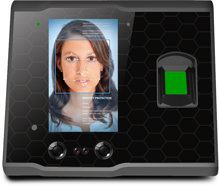
The reader is suitable for recording and controlling personnel access using facial recognition, biometric fingerprint scanning, or card/chip. Communication is carried out via WiFi or TCP/IP.
The system does not store any biometric or sensitive data, only a mathematical code. The only exception is the use of a photo from the access reader, which is not necessary for the system to function. It serves merely as a visual aid, for example, in the attendance overview. The use of photos can be completely disabled.
You can find the SYSF203TP reader in our e-shop, or contact your sales representative.
1. Editing the reader from the web application
model: Face
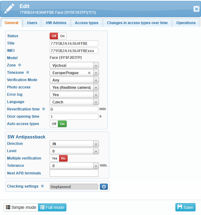
IMEI is a unique identifier of the reader and must be entered correctly for the device to communicate properly.
Readers can be assigned to different zones, for example by building or floor. In the access overview, you can then filter entries by these zones.
User verification is carried out using facial recognition, fingerprint, or card. It is also possible to configure different combinations of verification methods:
Fingerprint or card
Face only
Fingerprint only
Card only
Card + fingerprint
Face + card
Face + fingerprint
The most flexible option is to allow any verification mode.
In the General tab, you can also enable or disable the following functions:
Photo access – takes a photo during access entry. This serves as a visual supplement, which can be used for example in the presence overview or access overview.
Error log – the terminal stores records of errors that occurred during its software operation.
Reverification time – the period during which a user can verify again without sending another event to the server. Reader menu → Settings → Log → Verification time (min). Default value = 0 s.
Door opening time – the period for which the relay remains activated to open the door. Reader menu → Settings → Access → Door open time (s). Default value = 5 s.
Auto access types – when a user performs access on the reader, the type of access is detected automatically, without the need to select it on the reader’s screen.
SW Antipassback – a function that ensures a user cannot repeatedly use the reader to enter or exit without first performing the opposite action. This prevents misuse of the system and guarantees correct tracking of users’ movements.
You can also set the time for checking the settings, when the terminal configuration is compared with the system configuration.
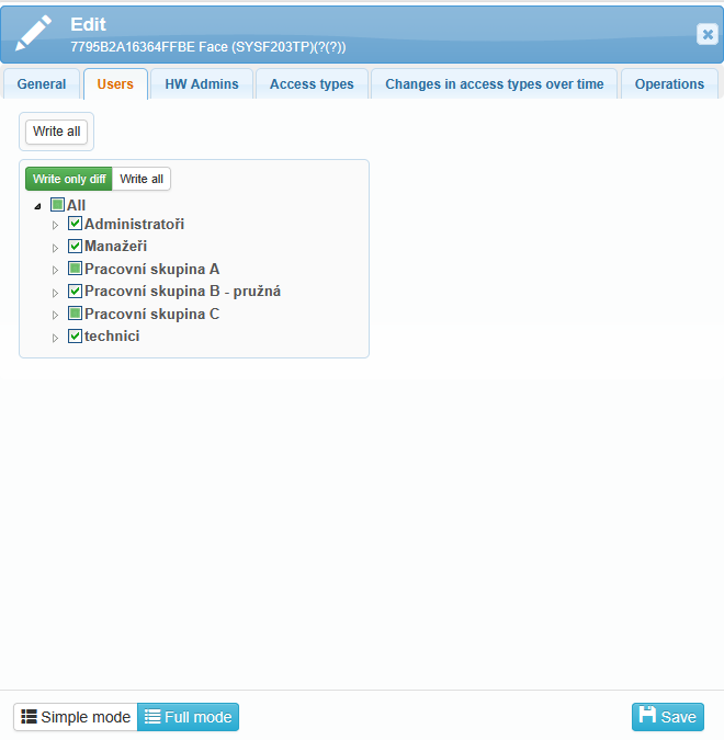
To use the reader, users must be assigned to it.
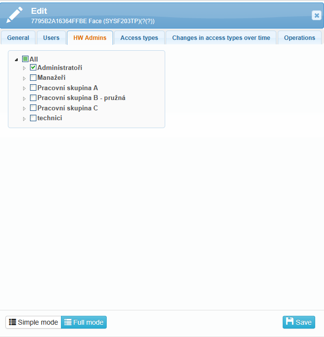
In the HW Admin tab, you can select users who have permission to manage and configure the selected reader.
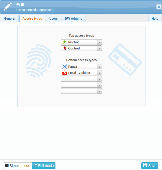
In the Access types tab, you can assign access types to individual buttons on the reader’s screen.
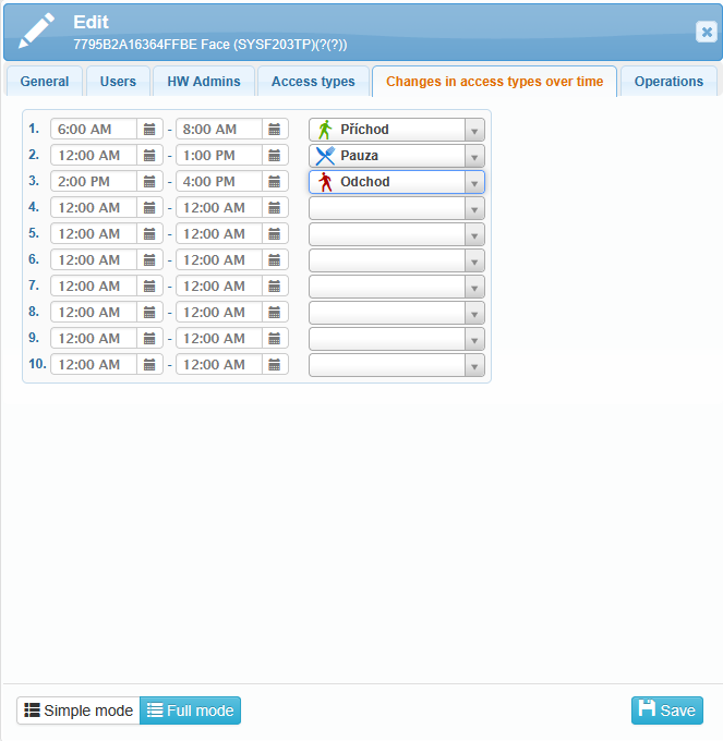
The Changes in access types over time tab is used to set scheduled time intervals during which the access types available on the reader automatically change.
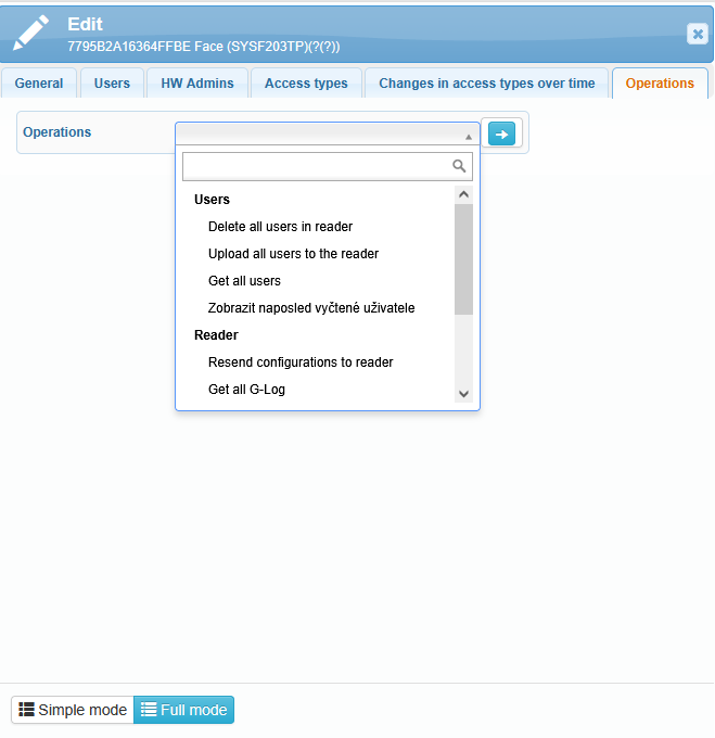
On this tab, you can perform various operations related to the users stored in the reader or to the reader itself.
Delete all users in reader – this operation deletes all users stored in the reader; users will no longer be able to use this reader for access.
Upload all users to the reader – this operation uploads all users stored in the system into the reader.
Get all users – this operation retrieves and displays all users currently stored in the reader.
Show last read users – this operation displays the list of users who were last recognized or read by the reader.
Resend configurations to the reader – this operation re-uploads all configuration settings to the reader (based on the edit form).
Get all G-log
Delete G-log
Reboot – this operation restarts the reader.
Synchronize time – this operation synchronizes the time on the reader.
Read statistics – this operation displays statistical data from the reader, such as access counts, successful and failed authentication attempts, user login times, and other metrics.
G-log – a list of events that occurred on the reader.
We recommend performing operations with caution. Uploading data (depending on its size) may temporarily limit the reader’s operation.
The following section Edit Reader in the Administrative Interface on the Device is for informational purposes only and is not required for normal reader operation.
All reader configuration, as well as loading of user authentication data, is performed in the SYSDO web or mobile application.
2. Editing reader in the administrative interface on the device
The little house icon in the upper left corner of the reader’s screen indicates access to the administrator interface. If the reader has a user loaded with administrator rights (Administration – Users – edit user – Permissions tab – HW Reader Administration), verification of this authorized user is required.
The administrator interface offers four main menus: User, Settings, USB Drive, and System Info.
Enroll
Enroll Button
Select the Enroll button to add a new user. The displayed form offers preset values for enrolling the new user, which can be edited.
The User ID field displays the first available user ID. The ID is a unique number assigned to the user, which identifies them within the system.
Clicking the Name field opens a virtual keyboard allowing you to enter the user’s name.
In the Level field, you can select the user’s permission level: User, Manager, or Administrator.
By clicking the OK button, the data is saved, and the next screen for registering the user’s card, face, fingerprint, and other settings is displayed.
To register a face, fingerprint, card, or enter a password, follow the on-screen instructions and voice prompts.
Photo – registers a photo of the user, which can be displayed during authentication on the reader. Note: The photo is not used for actual identity verification!
User Time Zone – assign up to five time zones in which the user will have access rights. By default, Time Zone 1 is assigned, which is permanently valid.
Fingerprint Alarm – enroll a fingerprint whose use grants access and simultaneously triggers the alarm output.
The alarm can be deactivated from the main menu.
Delete
Pressing the Delete button opens a user selection table. After entering the user’s ID, another table appears where you can choose which item to delete (Face, Fingerprint, Card, Password, Photo).
The option Delete All will remove all of the user’s data.
Edit
Pressing the Edit button first displays a table with a list of users. Clicking the row of the selected user opens the same form used when initially enrolling the user.
Basic
Language – Select the language displayed on the keyboard (English, Czech).
Sound – Enable/disable the sound signal when touching the display.
Volume – Set the volume of sound signals and voice messages (range from 1 to 10).
Access mode type – Define the labels for available access types (arrival, departure, doctor, etc.).
Automatic change of access mode – Set the time periods for automatic switching of access modes.
Bell settings – Configure activation time and select the bell tone.
Number of rings – Set the number of rings upon bell activation (range from 0 [disabled] to 255).
Section – Edit the name of the section (branch, department, etc.) to which the user may belong.
Advanced
Verification mode – Choose the method of user verification (face, fingerprint, card individually, or combinations including password).
Face detection sensitivity – Set the detection sensitivity (normal, low, high).
Date and Time – Set the date and time, including format and time zone.
NTP Server – Set the server address for time synchronization, used if the device is connected to the internet.
Time synchronization – Synchronize the time if the device is online and the NTP server is set.
Photo settings – Choose which photo to display after successful verification (none, uploaded photo, or realtime camera).
Use error log – Enable error logging for later troubleshooting.
Admin limit – Set the maximum number of users with admin or manager permissions (maximum is 5 managers).
Calibrate sensor – Launch sensor calibration to adjust to ambient lighting conditions. This may take up to a minute; completion is indicated on-screen and via voice message.
Firmware upgrade – Update the reader’s firmware from a connected USB flash drive.
Factory reset – Restore factory settings; user database remains intact.
Power
Restart at – Set a specific time to restart the reader (similar to power off/on).
Sleep mode after – Set the time of inactivity after which the reader enters sleep mode (0 to 9999 minutes). In sleep mode, the display shows the time, fingerprint sensor is deactivated, and the reader wakes up with detected motion.
Communication
In the Communication menu, configure connection settings for internet access (TCP/IPv4, TCP/IPv6) and view the device’s MAC address.
You can select between DHCP (automatic IP assignment) or manually enter connection parameters.
In the WiFi section, configure wireless connection settings, enable/disable WiFi, etc.
Log
This menu allows you to set warnings for when the log files approach maximum size.
Access
Define time zone – Set up to 50 time zones to control access permissions.
Door unlock time – Set the duration the door relay stays activated.
Door open timeout – Set the maximum time the door can remain open before triggering an alarm. Requires a door sensor and correct sensor type (NO – open, NC – closed).
Door sensor type – Choose the type of connected door sensor (none, NO – open, NC – closed).
Tamper monitoring – The tamper switch triggers an alarm if the device cover is removed. It does not react to the removal of the reader from its mounting base.
Wiegand output type – Select the Wiegand output format and card number bit length.
Test
This menu contains basic hardware tests of the reader. You can run them individually or use “Test All” to run them sequentially.
The USB Disk menu includes available operations for working with a connected USB flash drive, primarily for downloading or uploading the user database. This allows you to transfer the user database from one reader to others.
Download new time log
Download all time logs
Download new admin log
Download all admin logs
Download user database
Download user database (XML)
Upload user database
Upload user database (XML)
Enroll Info
This menu displays the number of registered users, enrolled fingerprints, faces, etc.
These values are for display purposes only and cannot be edited in this menu.
Device Info
The Device Info section provides information about the hardware and firmware versions.
Advanced
View Time Log – Displays an overview of access records for a selected user
View Admin Log – Overview of operations performed by users with administrator permissions
View User List – Displays a list of users including the number of enrolled fingerprints and facial templates
In the bottom right corner of the reader’s screen, a connectivity icon is displayed.
If this icon is overlaid with a red cross, the reader is not communicating.
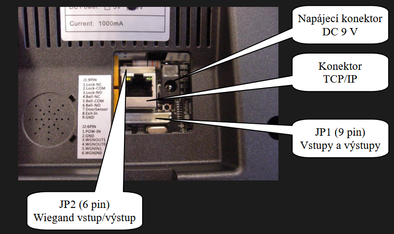
3. Description of connectors
- Power Supply (Positive Pole)
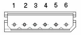
- Power Supply (Negative Pole)
- Wiegand Output 1 (WGNOUT1)
- Wiegand Output 0 (WGNOUT0)
- Wiegand Input 1 (WGNIN1)
- Wiegand Input 0 (WGNIN0)
- Lock Relay NC (Normally Closed)
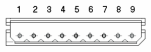
- Lock Relay COM (Common)
- Lock Relay NO (Normally Open)
- Bell Relay NC (Normally Closed)
- Bell Relay COM (Common)
- Bell Relay NO (Normally Open)
- Door Magnetic Sensor
- Door Open Button Input
- Power Supply Negative Pole
4. Frequently asked questions (FAQ)
Why are employee accesses not visible in the access overview?
It is possible that the reader is not communicating, and therefore the data from the reader has not been transferred to the system. Please check the connectivity of the reader.
Users can still register accesses even if the reader is not communicating. These accesses are stored in the reader and will be sent to the system as soon as the reader reconnects.
How can you tell if the reader is not communicating?
On the reader’s screen, a connectivity icon is displayed in the lower right corner. If this icon is overlaid with a red cross, the reader is not communicating.

In Administration - Readers, connectivity can be identified by the Last Data column. Green coloring indicates normal operation, while orange or red colors indicate the reader is not communicating. The same color coding is also used in the application header, where colored bubbles with numbers are displayed.
If a user is set as a HW manager of the reader (Administration - Users - user edit - Permissions tab - HW Reader Management) and has a contact email filled in (Administration - Users - user edit - General tab - Contacts), they will also receive a warning email in case the reader stops communicating.
Why is the reader not communicating?
Possible reasons include:
- Incorrectly entered IMEI number
- In the reader’s administrator interface (house icon on the reader screen in the top left corner), the unique reader identifier (IMEI) is displayed in the bottom right corner
- Check if the IMEI matches the IMEI entered in the web application (Administration - Readers - edit reader - General tab - IMEI)
- IMEI should be entered without dashes!
- Incorrect communication settings with our server
- The reader is not connected to the internet
- Check if the cable is properly connected and not damaged
- Verify that the internet connection works on the used cable (e.g., connect the cable to another device and check the status)
- Check if there is an issue with the reader’s connection (e.g., connect the reader to a cable you know works and check the status)
- Internal network settings blocking communication, such as firewall or port restrictions (ports 4000 and 123)
- This issue needs to be resolved with the company’s network administrator
How can a user authenticate using a password?
The procedure for password authentication on the Face reader model (SYSF203):
- On the reader screen, select the lock icon (top right corner).
- The reader will prompt you to enter the user ID (number) – you must enter the user’s PIN from the SYSDO system (Administration – Users – edit user – Authentication tab – Codes section – PIN).
- The reader will then prompt you to enter the password – you must enter the user’s Password from the SYSDO system (Administration – Users – edit user – Authentication tab – Codes section – Password).