Installation Instructions
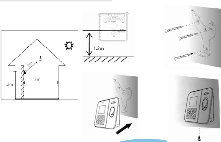
Install the device indoors, at least 3 meters from a window and 2 meters from any light source.
Do not install the device near windows or in outdoor environments.
Installation Steps:
Stick the mounting template onto the wall and drill holes according to the markings on the template.
Attach the mounting bracket to the wall using screws.
Place the reader onto the bracket.
Secure the reader to the bracket using the supplied screw.
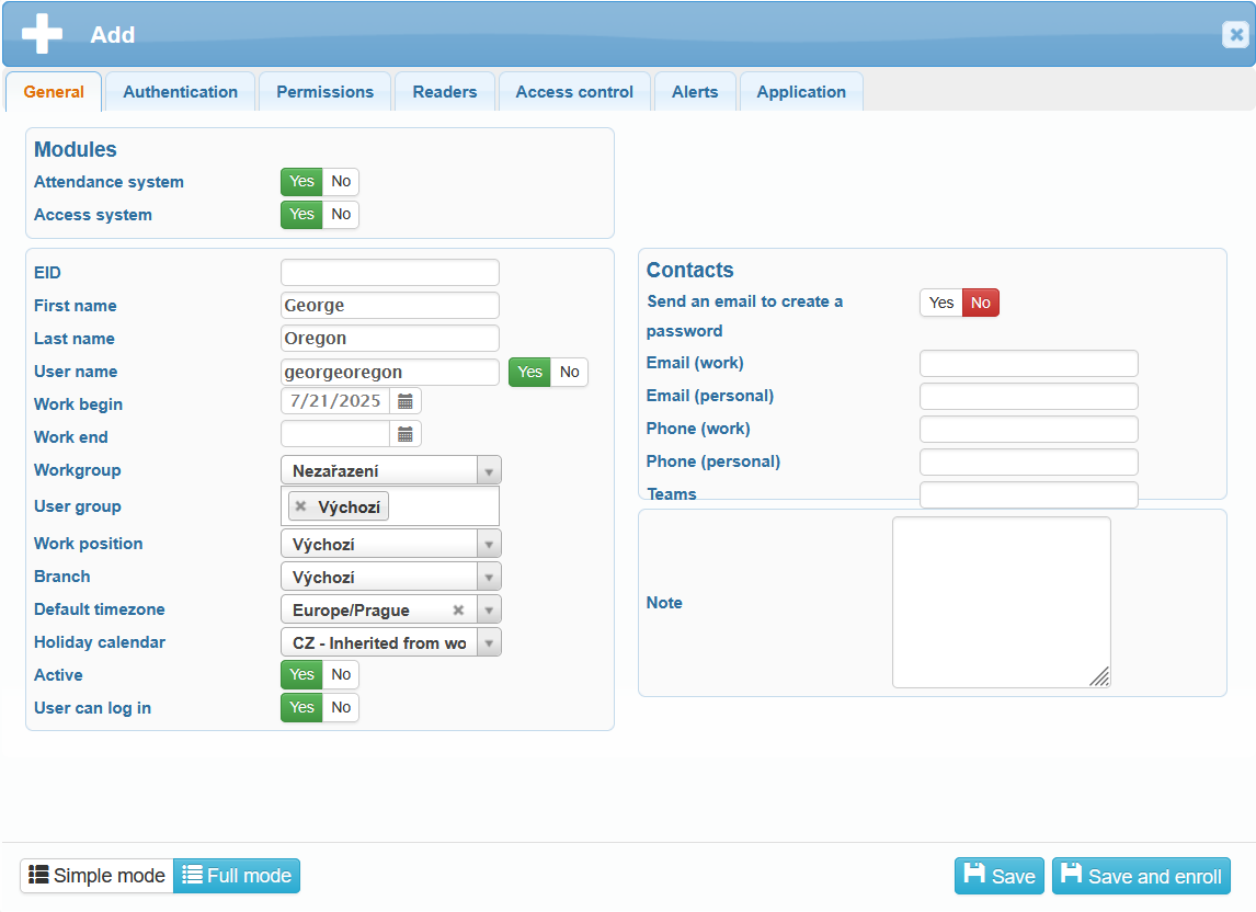
You can register a new user by navigating to Administration – Users – button ![]() . Fill in the user information and click
. Fill in the user information and click ![]() .
.
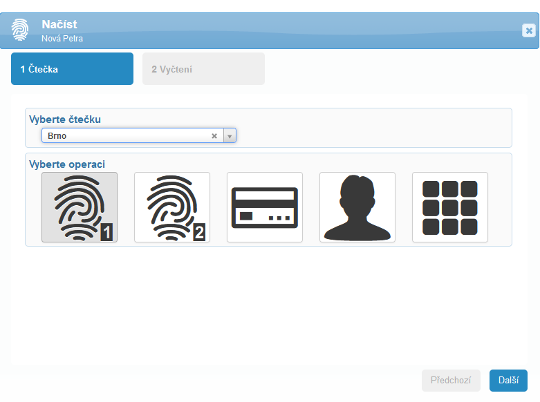
To upload verification data (fingerprints, face, card/chip), a window will open where you select the reader on which the user will be registered. Then, choose the operation – uploading a fingerprint, face, or card/chip. Click Next.
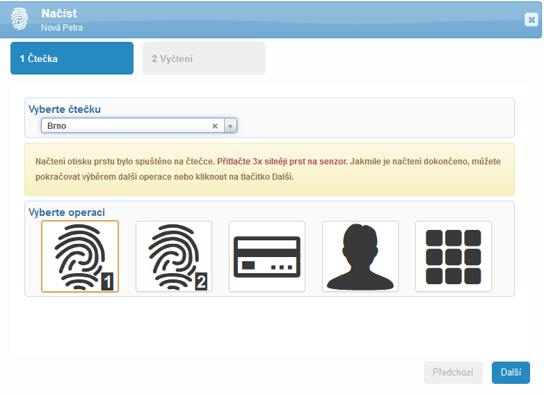
The reader will begin the scanning process and prompt the user to place their finger, position their face, or present their card. The system will display a message indicating that the scanning has started on the reader. Once the user completes the required steps for data capture, click Next.
The data will be retrieved—wait until the progress indicator turns green and shows Saved. Then click Finish.
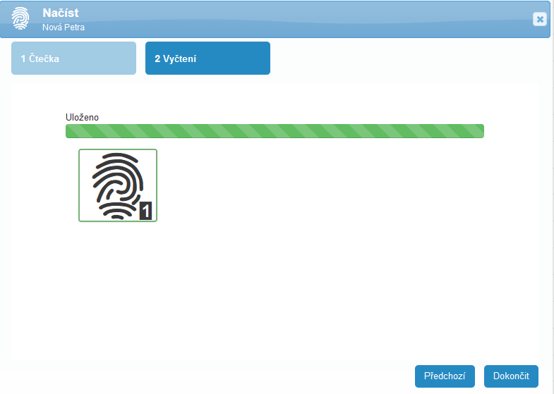
After uploading and saving the login data, ASSIGN THE USER TO THE READER – without assignment, the reader will not recognize the user.
You can assign the user in two ways:
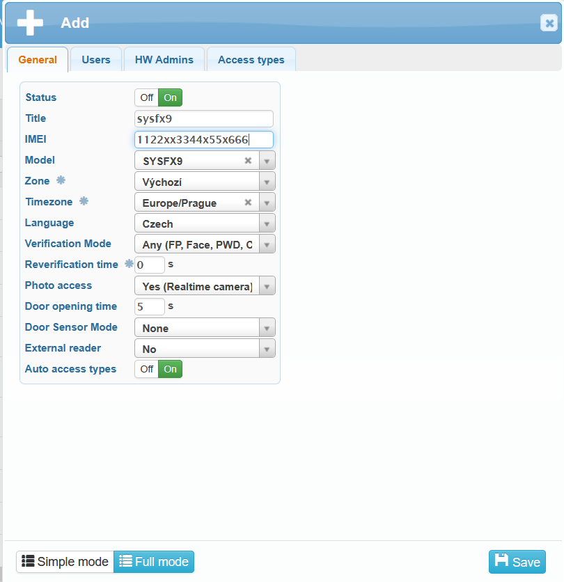
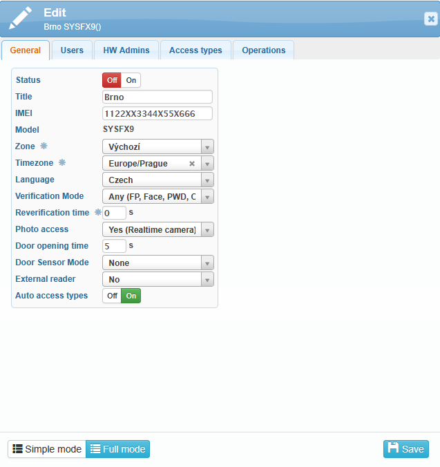
- Status On/Off
- Title
- IMEI
- Model SYSFX9
- Zone – if you have created Zones in SYSDO (for example, according to branches, company departments, etc.). If editing is not possible, the setting is inherited from the connected reader. Configure it on the connected reader.
- Timezone – if editing is not possible, the setting is inherited from the connected reader. Configure it on the connected reader.
- Language
- Verification mode – select how users will be able to authenticate.
- Reverification time – the time during which you can re-authenticate. During this period, no event is sent to the server.
Reader menu -> Settings -> Log -> Verification time (min). Default value: 0 s. - Photo access
- Door opening time – relay activation time – not relevant if the reader is not connected to a door.
Reader menu -> Settings -> Access -> Door opening time (s). Default value: 5 s. - Door sensor mode – not relevant if the reader is not connected to a door.
- External reader
- Auto access types – we recommend enabling this option – the SYSFX9 reader does not have a touch display. With automation enabled, access types are assigned according to the defined shifts and schedules, so there is no need to select access types manually (via buttons). The access type is detected automatically (no need to select it on the reader).
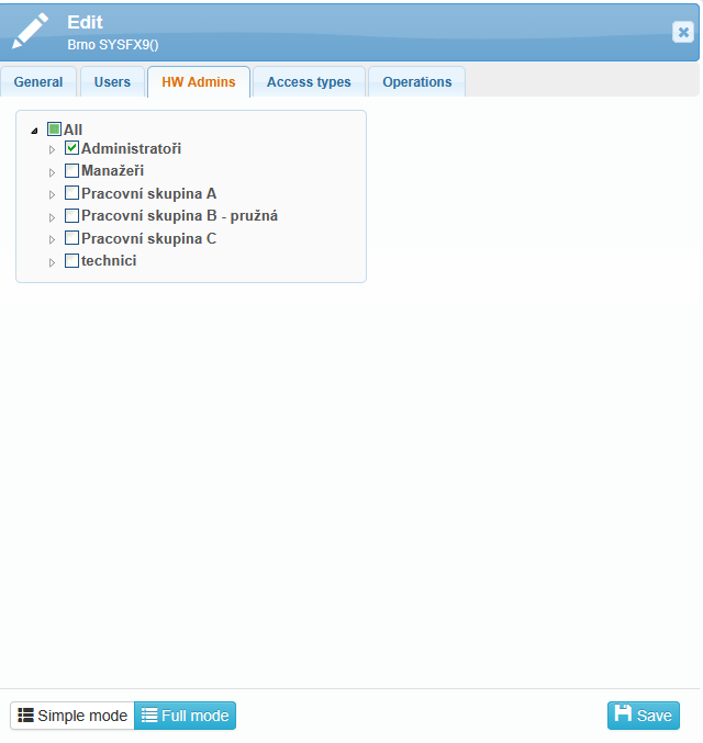
Here you can select who will be allowed to authenticate on the reader. Expand the user tree using the small triangles next to the checkboxes.

If you don’t want anyone other than the attendance administrator to be able to change the reader settings, set up a hardware administrator for the reader. When attempting to access the reader menu, administrator authentication will be required – fingerprint, face, card, or PIN – depending on your configuration.
Assign as administrator someone who is ALWAYS present in the company. If communication fails and the designated administrator is absent, it will not be possible to access the reader settings. You can assign multiple administrators.
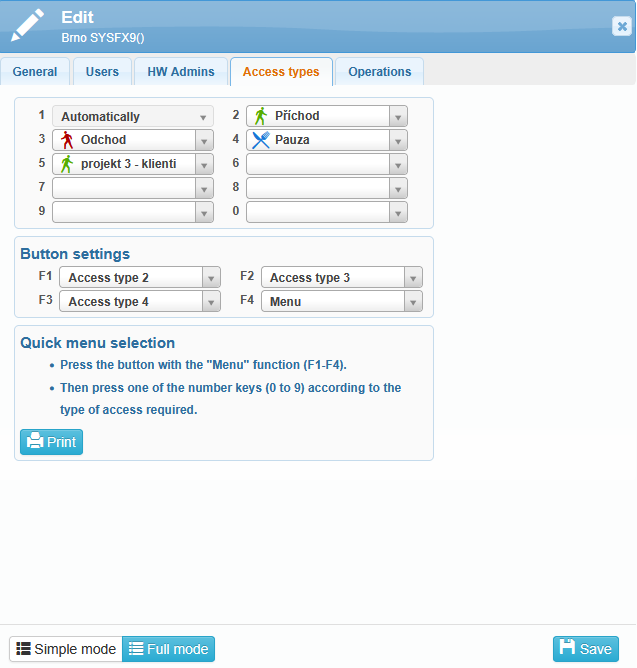
Here we select which access types are available to users.
BUTTON SETTINGS
If button automation is turned off and button selection is required:
Access Type 1 will always remain empty, or “Automatic” – it cannot be changed.
Right at the setup stage, we recommend printing the button labels and placing them near the reader.
We suggest assigning the most commonly used access types to buttons F1–F3 (i.e., Check-in, Check-out, Break) and assigning F4 to provide access to other options – MENU.
Verification can be set as follows:
The user first selects the access type and then authenticates.
The user first authenticates and then selects the access type.
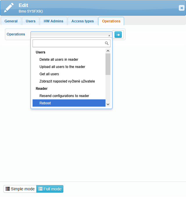
The Operations tab allows remote data retrieval from the reader and remote reader control.
User operations:
delete all users in reader
upload all users to the reader
get all users
display the last retrieved users
Reader operations:
resend configuration to reader
reboot
read settings
read info
get time
open the door
get all G-log
list of unknown verifications
read F buttons settings
firmware upgrade
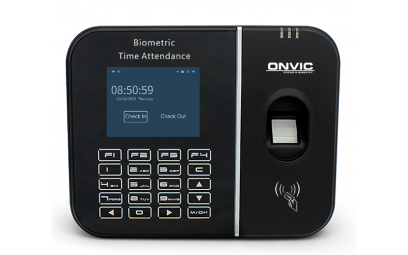
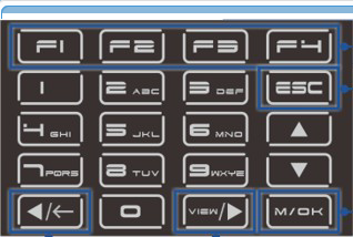
The SYSFX9 reader does not have a touch screen. It is operated using the buttons located below the display. To select the access type for authentication, use the F1 button, then navigate with the arrows. The left, right, up, and down arrows are used to move through the menu and access types. Confirm selections with the M/OK button. This button is also used to enter the Reader Menu. To go back or cancel a selection, use the ESC button.
When entering text, the left arrow deletes characters.
The right arrow switches between uppercase letters, numbers, and special symbols.
The F4 button provides a shortcut to Communication settings.
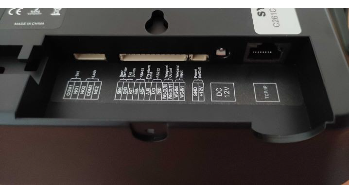
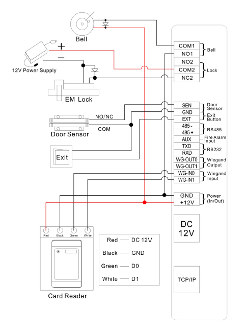
5-pin connector – for example, for connecting a door lock
12-pin connector – for Wiegand communication, RS485 communication, Exit button, etc.
Power In/Out
Power supply – with the included 12V adapter
TCP/IP – Ethernet (network) cable